
Gear Legs

Last updated November 8th, 2022!?  Time sure gets away from you sometimes, doesn't it. Woof..

 A lot of time was spend figuring out main landing gear legs. The first step was taking the info from the Piper drawings and laying out the gear v's full size on my table, then jigging the parts in place.

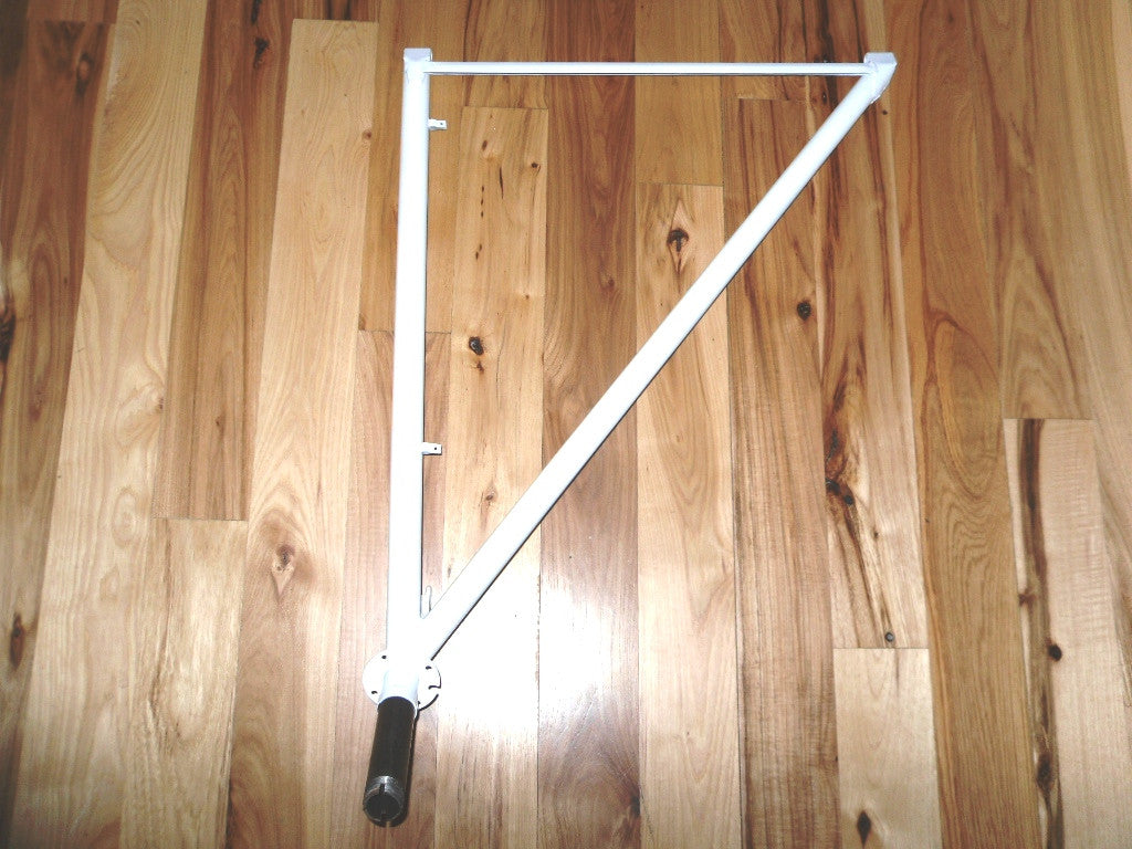
 This is what we're building. The left side of the picture would be facing the front of the aircraft.

 Piper J-3 Style Landing Gear (Left) 3/8" Bolts

And here's the jig laid out on my table. The nearer jig sets the relationship between the forward tube and the axle. The farther jig aligns the forward and rear tube as well as the bushings on which the gear leg will pivot.

With the jigs laid out it's time to manufacture parts. First came the pivot bushings, and they were a bit of a process. First the little U-shaped piece of metal that holds the bushing needs to get bent to shape. I made a little die the right size to bend the material in my vice. After the U is bent it then gets a notch ground out to fit around the bushing and the bushing is welded in. The jig has bolts pushed through the table where the bushings go to register them properly. 


Tubing is then slid up against the bushing assemblies, marked, and cut to fit. Paper patterns from an online tube-notching calculator help get everything cut to the right shape. The next problem is one of fitting the tubing to the bushing assembly. The tubing is round (obviously) but the base of the assembly is square. Leaving it like this would make welding them together and adding the subsequent reinforcement strap very difficult. I took some scrap tubing and tried a couple different techniques to make them fit together. Ultimately I was able to heat the end of the tube 1/4 at a time and hammer it flat until I got a pretty even square shape. 

A similar technique was used on the rear tube, but because this meets the bushing assembly at an angle only two sides were flattened. The assembly was then tacked on, the overhanging tube notched, heated, and bent back onto itself.
 
 That sets most of the actual V to rest. Next I had to move onto the axle. Well, actually, the axle is also a two piece assembly. There is the thinner outer sleeve which welds to the V and the thick inner axle. Both the outer sleeve and axle need ears cut on one end then drilled and flattened. I cut the ears into the first one then heated it to flatten out the ears. I had cut the notch too square and the tube was now scrap. I ordered some more tubing. In the meantime I lopped the ears off, marked them out again, and tried cutting a rounder notch. I was much happier with how this one turned out and duplicated it when the new tubing came in.
With that part done, the axle then needed to be threaded for the axle nut. I managed to find a die the right size to cut the threads, but couldn't find a reasonably priced die-wrench. So I made up a tool to keep the die aligned with the axle so I could turn it with a wrench for the actual threading operation. More scrap tubing for the win!
 
And the axle nut threads on perfectly.
 
With those parts all made and the weather warm enough I could finally start welding the gear V's. The front and rear tubes were tacked together then fully welded. The inner and outer axle were welded together as one assembly and then jigged up and tack welded to the V. That's what's happening in the following pictures. There's more, but that will have to be saved for the next post.


Comments

Popular posts from this blog

Fittings. How fitting.

  Not much has happened on the Ace this year. The winter was long and spring has been very cold, so I spent a long time waiting for the garage to warm up. Now that there's a little heat down there I've been making some headway on the next step of my wing build: fittings. I copied the parts off the plans into CAD and then printed them onto cardstock to use as patterns when laying fittings out on the steel stock.    First I tackled the brackets that will hold the pulleys for the aileron cables. I have a lot of extra material in case I had to remake these. The next step was to bend up my fittings. There is one fitting that mounts to the forward side of the strut which gets bent to a 90° angle. The fitting which mounts to the aft side of the spar gets bent at about an 85° angle. I forget the exact number, but don't feel like looking it up at the moment. Next I cut out the aileron control horns. My Harbor Freight porta-band chucked into my vice works well for cutting thes

10 months in under 10 minutes.

I don't feel like going into depth on every little aspect of work I've done over the last 10 months, so I'll hit the highlights and if anyone has questions, feel free to comment and I'll elaborate.  As the year started the garage was cold. With a propane heater it would get warm enough to work for a few hours, but because 4130 steel is an air-tempered alloy, it needs to be sufficiently warm out for welding. Long story short; I can't weld, so I make parts. I plugged away making little bits so I can use them when it comes time to build a new assembly. The landing gear legs and spring struts have metal straps to reinforce the bushings in the ends. I knocked these out in a couple days after work. Likewise, the tabs that will become door hinges and the fittings for the tailwheel were cut, drilled, and deburred. As it warmed up and I got an order of laser-cut parts the aileron control arm and pulley brackets were welded to the torque tube for the control stick.  I also cu

3-D and waiting.

On January 18th I posted my last blog update; both fuselage sides were tack welded. That was seven months ago now. I should update more regularly. Okay, self-flagellation over, let's get to the content! Once both fuselage sides were tack welded, I pulled all the jig blocks off the table, elected not to repaint again, and just laid out the stations for the top view of the fuselage. We lay out the top view because the top of the fuselage is flat which makes it a lot easier to jig things up if you lay out the fuselage upside-down. With the top view lofted out on the table I could start adding in jig blocks starting in the cockpit area where the sides are parallel. A stick and some clamps help hold the sides parallel for this photo op.  Now may be a good time to mention, if I haven't already, that I am widening this fuselage from stock. The original Jr Ace (Model E) was 33-1/8" between tubing centerlines at the widest point. This makes for a pretty cramped space when two peopl